Veteran
Posts: 148
 
Location: Mandurah, Western Australia | Sorry about this post, its a while since I did one and its got me stumped how to mix text and photos. All the photos are at bottom and I cant move them. Thought I was in P15-D24 forum??
And it wont let me delete it??
I picked up a RHD Suburban in September 2014, with V8, auto and a Hollywood steering wheel. It was licensed but needed lots of work to make it roadworthy. By mid 2015 it was back on the road but the steering wheel was way off centre and the turn signals were intermittent. The wheel was very hard to remove as it had been installed with splines mis-aligned. There is only one correct location and it took a lot of filing to clean up the splines. After removing the wheel and horn switch it was obvious that the turn signal switch operating plate was damaged which was preventing the switch and self-cancelling from working properly. I made temporary repairs, put it back together and ordered a NOS switch operating plate #1595219.
Fast forward to 2023 and on a short trip to a club meeting the turn signal decided to give up. It is not safe to drive like that in modern traffic, weather here was too hot for sanding the last ’38 mudguard, so off came the wheel again, much easier this time.
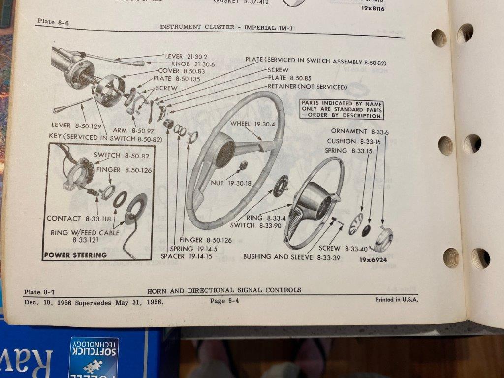
There is no diagram of the switch or steering wheel in the shop manual or the standard parts manual, but I did find a diagram for the Savoy in an Export parts manual that I was lucky enough to get from ebay Germany. I decided to document the process.
Here is the parts diagram and the associated parts list:
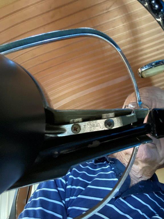
First step is to disconnect the battery, then remove the four Phillips head screws under the arms of the Hollywood wheel and lift off the centre.
Unplug the horn wire then undo three locating screws for the horn switch to remove the horn switch and horn ring. These screws have fragile insulating spools which are available on ebay.
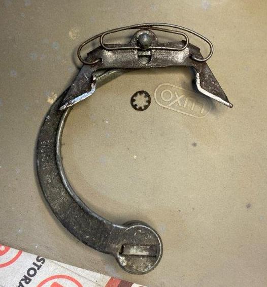
Here is the horn ring
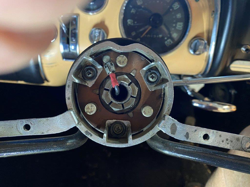
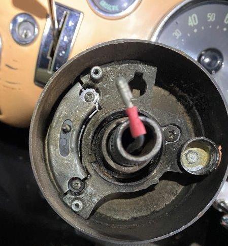
Undo the wheel nut then remove the wheel using a puller if needed. This exposes the turn signal mechanism.
Unscrew and remove the turn signal lever. It has two small flats near the base where it can be gripped. Then remove the two small screws holding the bridging plate (which helps locate the mechanism) and lift out the switch mechanism which includes the bridging plate, the switch operating plate and the switch arm.
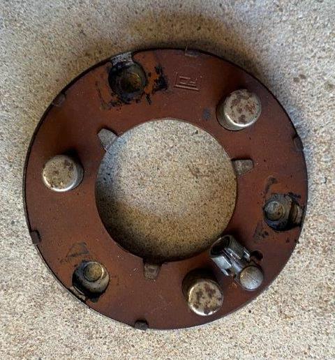
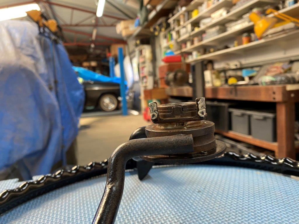
This is the switch operating plate and arm
Below this mechanism is the turn signal switch which is held in by two more screws. This switch incorporates the wiring loom so to remove it is a major exercise. In my case the switch was ok so it was left in place.
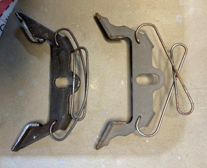
To remove the switch operating plate from the arm, very carefully prise off the star clip using two jewellers’ screwdrivers from underneath.
Here is the old operating plate on the left and the new on the right. The ends of the old plate were badly chewed and the spring was bent.
Install the new plate on the arm, replace the clip, place the parts in the steering housing and secure with the bridging plate and two screws, then install the turn signal lever. Tape up the horn wire, temporarily install the wheel, reconnect the battery and test the indicators function correctly. When I did this, I found that the switch cancelling fingers under the boss of the steering wheel did not fully engage the new switch operating plate, which must have been what caused the old plate to fail. The fingers are on a ring which is a press fit on the boss so I was able to lever the fingers down on the steering wheel boss until they engaged fully and operated properly.
Edited by westaus29 2023-06-13 10:13 AM
 (a1.JPG) (a1.JPG)
 (a2.JPG) (a2.JPG)
 (a3.JPG) (a3.JPG)
 (a4.JPG) (a4.JPG)
 (a5.JPG) (a5.JPG)
 (a6.JPG) (a6.JPG)
 (a7.JPG) (a7.JPG)
 (a8.JPG) (a8.JPG)
Attachments
----------------
 a1.JPG (121KB - 65 downloads) a1.JPG (121KB - 65 downloads)
a2.JPG (61KB - 67 downloads)
a3.JPG (104KB - 70 downloads)
a4.JPG (58KB - 66 downloads)
a5.JPG (42KB - 75 downloads)
a6.JPG (44KB - 74 downloads)
a7.JPG (59KB - 66 downloads)
a8.JPG (107KB - 69 downloads)
|


